Building a Signal Flow Diagram
As the data will be retrieved either via GOOSE or Reports, the nodes being dragged will have to be enabled for either GOOSE or Reports. Nodes that can only be polled cannot be added to the Signal Flow Diagram. The availability of a node through GOOSE or Reports can be established by examining the ‘Used in GOOSE Control(s)’ and ‘Used in Report Control(s)’ columns of the Data Miner. If a node is available through both GOOSE and Report, the source is determined by the GOOSE and Report buttons in the Data Retrieval Method section of the Data Miner Ribbon Bar. If both the GOOSE and Report buttons are selected, priority is given to GOOSE. When a Data Attribute is dropped onto the Signal Flow Diagram, TSP will automatically issue the necessary subscription to the server if it is not already enabled.
If a Data Attribute containing external references from other Logical Nodes is added to the Signal Flow, those Logical Nodes are also added to the diagram.
The following screenshot explains the various options provided to ease the process of creating a Signal Flow Diagram:

- The Data Retrieval Method section determines the method that the Signal Flow should use to retrieve the data for the Data Attribute being dragged. The precedence of the methods is in the order of appearance (i.e. GOOSE/Report) in case the node has both GOOSE and Report enabled. If neither GOOSE nor Report is enabled on a node, it cannot be used in the Signal Flow.
- The Data Miner has a Factory Preset (GOOSE Publishers) to show only Data Objects that are available in a GOOSE stream so they may be easily added to a Signal Flow diagram.
- The Data Miner has a Factory Preset (Reported) to show only Data Objects that are available in Report so they may be easily added to a Signal Flow diagram. These signals can only connect Logical Nodes in the same device since servers do not normally communicate via Reports.
- The Data Miner column Input to LN’s identifies the Logical Nodes with an External Reference to each Data Object that is available in a GOOSE stream.
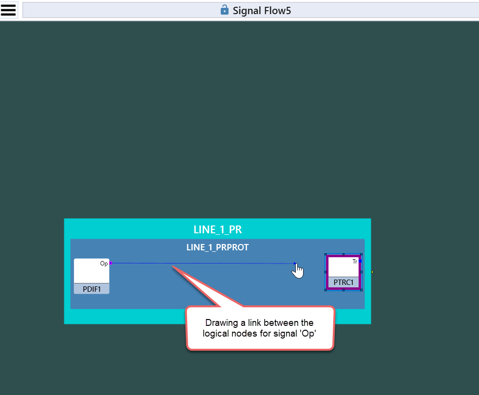
- Besides setting up the links between the nodes that refer to each other via external references, the Signal Flow also lets the user draw a link from an output to any node of choice.
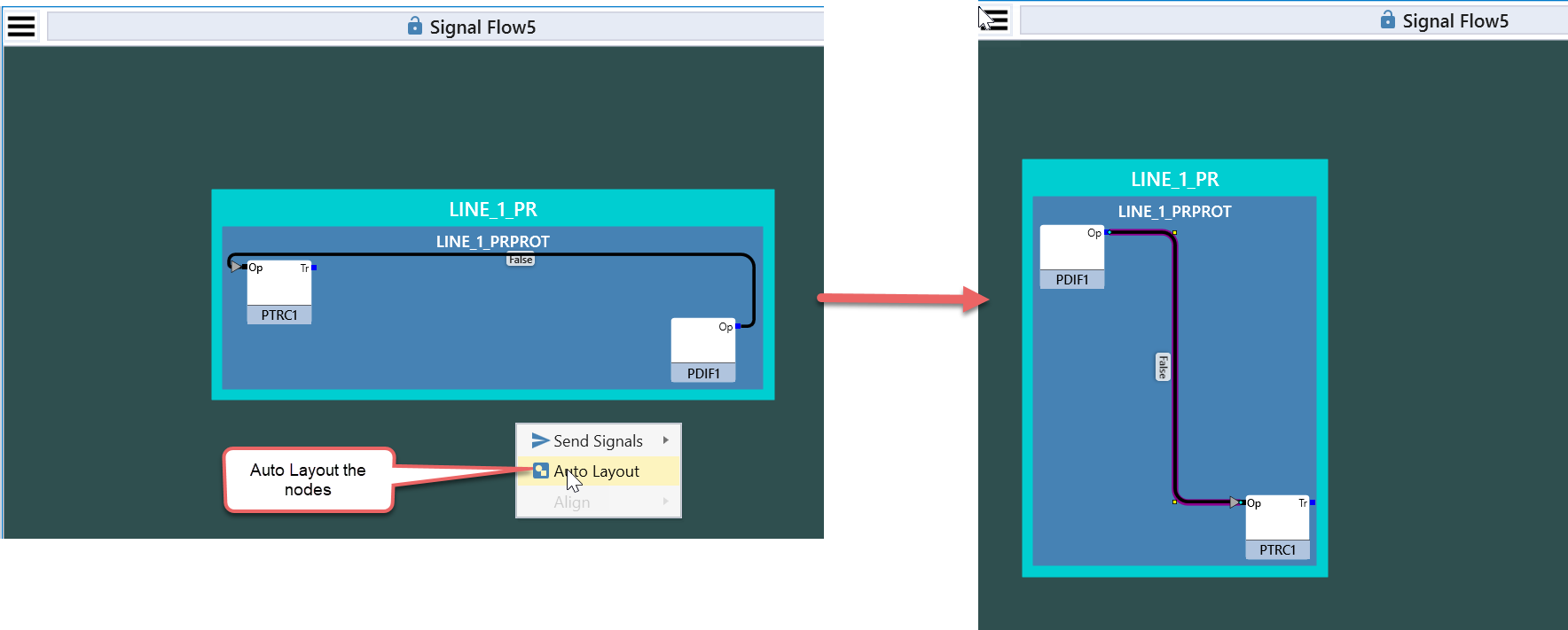
- The Signal Flow automatically lays out the logical nodes in the order of the flow of signals between nodes by default. One can choose to reset the arrangement of nodes by choosing the context menu option Auto Layout.